Type C Door Lock Wiring
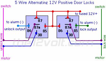
Door Locks 5 Wire Alternating 12 Volts Positive Type C Relay Wiring Diagram
Door Locks Actuators Reverse Polarity Positive Switch Trigger Type D Relay Wiring Diagram

Car Alarm Door Lock Wiring

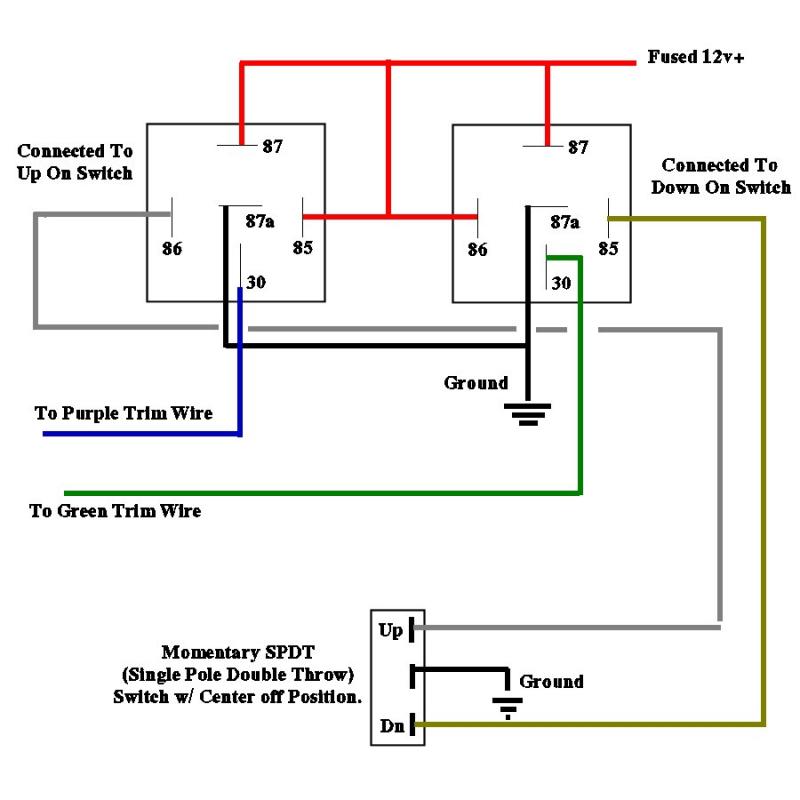
Installation Diagrams

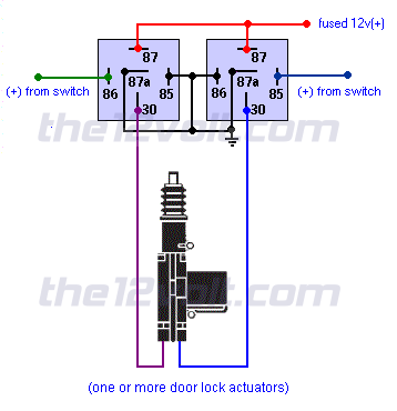
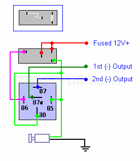
3 Wire Positive Door Locks Relay Diagram Door Lock System Door Locks Automotive Electrical
Wiring Diagram For Aftermarket Door Locks Car Audio Forumz The 1 Car Audio Forum

The switch when moved in either direction applies both power and ground directly to motor legs without the use of any relays.
Type c door lock wiring.
Multiple Wire Power Door Lock Systems Add Auto Lock Unlock
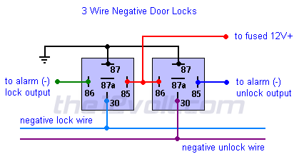
Door Locks 3 Wire Negative Type B Relay Wiring Diagram
Door Locks Single Pulse To Lock And Unlock Negative Pulse Relay Wiring Diagram
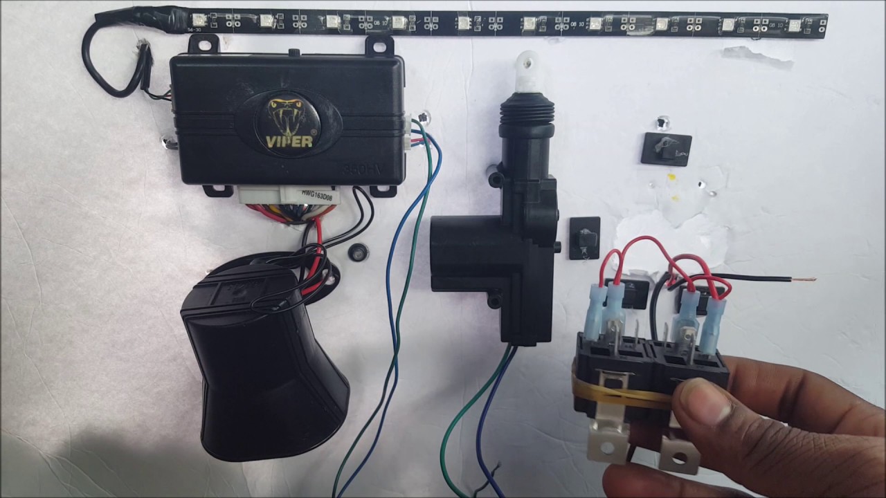
How To Wire Up A 5 Wire Door Lock Actuator Relay From Start To Finish Very Easy Youtube
Source : pinterest.com
